Principles of Railway interlocking is a huge and hard topic.
In railway signalling, an interlocking (IXL) is a system composed by a set of signal apparatus that prevents trains from conflicting movements through only allowing trains to receive authority to proceed, when routes have been set, lock and detected in safe combinations.
The main function carried out by an interlocking system is to set and lock routes related to each train located in an area under its responsibility, in order to ensure safe movements along the track.
Setting a route means following a request from the signaller or time-tabling system, driving each switch to the correct position, locking it there and maintaining that locking, until the train passes out the route affected.
The interlocking safety logic is mostly realized through control tables, a set of rules/constraints that must be observed and are an abstract specification for the area under the interlocking responsibility. The interlocking control tables are designed so that it is impossible to display a signal to proceed unless the route to be used is proven safe. In this way, no other train is allowed to enter a conflicting route until it is released by the interlocking system.
Over the years, the continuous technological development has enabled to achieve this function in an increasingly performing way.
Mechanical interlocking
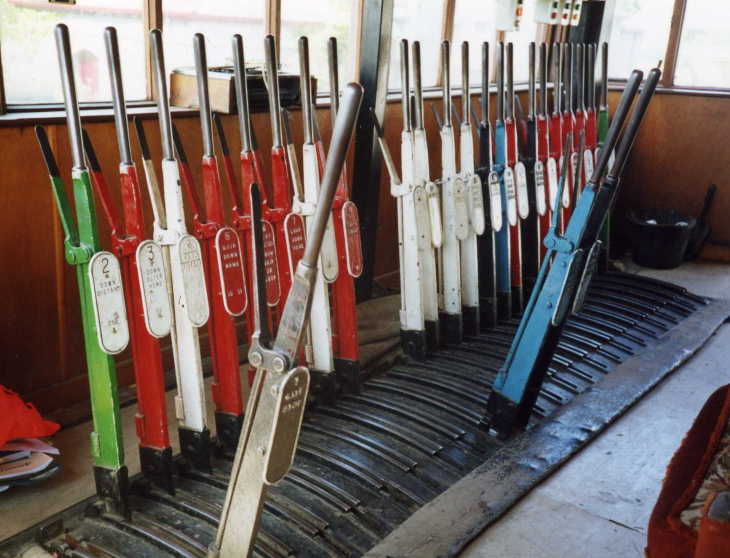
Mechanical interlocking provides the control of a railway area through the movement of individual levers, physically connected via wires and rods to signals, points, level crossing gates or barriers.
Within areas controlled with mechanical interlockings, the railway is interspersed with several buildings (signal boxes) next to the track, containing manually or remotely controlled operated signal levers.
Even if this is an old solution, mechanical interlockings (both manual and remotely controlled) are still in operation along the UK main line railway network, particularly around rural areas and not highly busy lines.
Relay/Geographical Interlocking
In Route Relay Interlocking (popularly known as RRI), the Control Rules are implemented through Boolean logic using electromechanical relays.
Thousands of relays are connected with any track movable device belonging to the area under the interlocking responsibility. Each track device can assume two different values so that its status can be encoded by a Boolean value (e.g. normal/reverse for a switch, clear/occupied for a track circuit).
The electro-mechanical status of the whole set of relays connected to the track identifies the “status of the railway” in a certain instant and it represents the input value for the interlocking system.
The command to set and clear the route for the train is taken in the form of button form the Station master’s console, also known as control panel. When a command is given:
1) The RRI checks if the command is safe AND
2) It activates the coherent set of relays, which lock the requested route through the electro-mechanical switching of the relay status.
The relays circuits are build using the station Control Table as the input document and the interlocking rules as the Logic. The Control table decides the possible movements of the train inside a station yard and its relationship with other stations.
In a typical RRI installation the number of relays used to implement this type of logic is in the order of thousands of relays. That implies high costs and timescale for wiring install commission and maintenance.
Solid State Interlocking (UK Solution)
The Solid State Interlocking (SSI) system was first developed in the 1980s and jointly exploited by British Rail, GEC (now Alstom) and Westinghouse (later acquired by Invensys and now Siemens Rail Automation).
SSI is an interlocking system built using Electronics replacing traditional electro-mechanical relays. The Same Interlocking rules or control equations used in RRI form the basis of this technology.
The relays used to form the logic circuits in RRI are replaced by software variables and only the final Output driving relays are needed. A processor evaluates where the virtual relays (Software Variables) using the interlocking equations, which are now in digitized form either as Algorithms, Boolean equations or state charts in the processor memory. The control rules equations are modified as software algorithms and are stored in the embedded system memory.
SSI implies a several advantages related to the oldest technologies, including:
– Minimal space taken
– Entire logic circuits are simulated in software
– Relay wiring cost is saved
– Installation time comes down drastically
– Maintenance is very easy
– Verification and Validation of Software is a formal documented process
The obsolescence of some of the specific system suggests that the future deployment of SSI installations will be very limited. However, two manufacturers now have proprietary “next generation” SSI-like products, called Westlock (property of Siemens Rail Automation) and Smartlock (developed by Alstom). These products are backwards-compatible with the classic SSI interlocking data and trackside equipment and suitable for the future ETCS deployment.
CBI (Computer Based Interlocking)
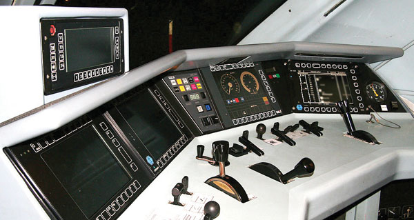
Computer Based Interlocking (also known as CBI) is the generic term for the most modern signalling interlocking products, implemented through computers rather than older technologies.
A modern CBI ensures higher availability, reliability and safety.
For more detailed information about railway interlocking principles and the most modern CBI systems, please click here.
Did you like this post? Would you like to be informed about the last railway signalling technical and commercial news? Join us on LinkedIn and stay updated!
railwaysignalling.eu | walk the rail talk


i didnot known about olid state interlocking
[…] is cleared only after all facing points are set correctly. This special arrangement is called Interlocking. The total basic railway signalling system depends on this Interlocking […]
[…] Interlocking is defined as the technique achieved through mechanical or electrical devices or agencies by which it can be ensured that before a signal is taken to “OFF” position, for the route, which the signal controls, is properly set and held, and at the same time all the signals and points, the operation of which may lead to conflicting movements, are locked against the feasibility of such conflicting movements. […]
Please send me fundamentals & logic circuit of Hitachi make EI,